Разница между диаграммой er и диаграммой классов
Содержание:
- Содержание:
- Содержание:
- Documenting an Existing Database Using Data
- ERD notations guide
- И снова про бизнес-процессы: живой опыт без теории
- Why use ER Diagrams?
- Weak Entities
- 2 Построение концептуальной модели
- Conceptual, Logical and Physical data models
- yEd Graph Editor
- Что такое диаграмма EER?
- Conceptual, Logical and Physical data models
- What is ER Diagram?
Содержание:
Диаграмма ER против диаграммы классов
Диаграммы ER (сущность-взаимосвязь) и диаграммы классов — это две схемы проектирования, которые разработчики программного обеспечения создают обычно на этапах проектирования жизненного цикла разработки программного обеспечения. Диаграммы ER являются продуктом техники моделирования отношений сущностей (ERM) для моделирования баз данных. Диаграмма классов, написанная на унифицированном языке моделирования, представляет собой диаграмму, описывающую структуру предлагаемой системы. Хотя нет необходимости иметь точное соответствие между классами в диаграммах классов и сущностями в диаграммах сущностей, обычно между ними существует некоторая значимая связь. Однако существует множество случаев, когда объект диаграммы ER отображается в несколько классов соответствующей диаграммы классов или один класс диаграммы классов отображается в несколько объектов соответствующей диаграммы ER. Но это полностью зависит от дизайнерских решений разработчиков программного обеспечения.
Что такое диаграмма ER?
Диаграммы ER являются продуктом моделирования отношений сущностей. Моделирование отношений сущностей — это процесс создания абстрактного и концептуального представления данных. Диаграммы ER в конечном итоге моделируют базы данных. В частности, он создает концептуальную схему модели данных. Основными строительными блоками диаграмм ER являются сущности, отношения и атрибуты. Сущность представляет собой вещь, которая может существовать независимо и может быть определена однозначно. Чаще всего сущность представляет собой объект реального мира, такой как автомобиль или служащий. Сущности можно рассматривать как существительные, возникающие при описании решаемой проблемы. Взаимосвязь показывает, как сущности связаны. Они похожи на глаголы в описании решаемой проблемы. Свойства сущностей и атрибутов называются атрибутами.
Что такое диаграмма классов?
Диаграмма классов (более точно известная как диаграмма классов UML) — это диаграмма проекта, которая представляет статическую структуру и поведение предлагаемой системы, определенной с помощью UML (унифицированного языка моделирования). Диаграмма классов показывает классы системы, отношения между классами и их атрибуты. Классы отображают абстрактное представление объектов реального мира, а отношения показывают, как каждый класс связан с другими. И классы, и отношения имеют свойства, называемые атрибутами. Методы в классах представляют или определяют поведение этих классов. Методы и атрибуты классов называются членами класса.
В чем разница между диаграммой ER и диаграммой классов?
Хотя ER-диаграммы и диаграммы классов — это две схемы проектирования, с которыми разработчики часто сталкиваются на этапах разработки проектов разработки программного обеспечения, у них есть свои ключевые различия. Диаграммы ER представляют абстрактное представление модели данных, а диаграммы классов представляют статическую структуру и поведение предлагаемой системы. Основными строительными блоками диаграмм ER являются сущности, отношения и атрибуты, но главными строительными блоками диаграмм классов являются классы, отношения и атрибуты. Диаграмма классов с большей вероятностью будет отображаться в реальных объектах, тогда как диаграммы ER чаще всего отображаются в таблицах в базе данных. Обычно отношения, обнаруженные в диаграммах ER, труднее понять людям, чем отношения в диаграммах классов.
Содержание:
Ключевая разница:
- Объекты: это может быть любое лицо, объект, событие или концепция, о которой необходимо хранить или поддерживать данные.
- Атрибуты: Характеристики объектов называются атрибутами.
- Отношения: описывает связь между сущностями.
Отношения далее делятся на необязательные и обязательные отношения. Другим важным термином, связанным с диаграммами отношений сущностей, является количество элементов. В отношении он определяет количество экземпляров объекта, которые могут (или в некоторых случаях должны) быть связаны с другим объектом. Таким образом, диаграммы отношений сущностей рассматривают реальный мир как совокупность различных типов бизнес-сущностей. Он определяет отношения между объектами, а также описывает атрибуты, связанные с объектами.
Сравнение между UML и ERD:
|
UML |
ERD |
|
|
Полная форма |
Унифицированный язык моделирования |
Диаграмма отношений сущностей |
|
Определение |
UML — это популярный и стандартизированный язык моделирования, который в основном используется для объектно-ориентированных программ. |
Диаграммы сущности-отношения используются в структурном анализе и концептуальном моделировании. Они часто используются для графического представления логической структуры базы данных. |
|
преимущества |
|
|
|
Условные обозначения |
|
|
|
Основные условия |
Класс, объект, ассоциация и атрибуты. |
Сущность, экземпляр сущности, отношения и атрибуты. |
|
Роль информации |
включены |
Не включено |
|
Комментарии |
Может быть графически представлен и прикреплен к любому объекту UML |
Нет комментариев в диаграммах ER |
|
цели |
|
|
Documenting an Existing Database Using Data
There are two reasons to create a database diagram. You’re either designing a new schema or you need to document your existing structure.
If you have an existing database you need to to document, you create a database diagram using data directly from your database. You can export your database structure as a CSV file (there are some scripts on how to this here), then have a program generate the ERD automatically.
This will be the most accurate potrait of your database and will require no drawing on your part.
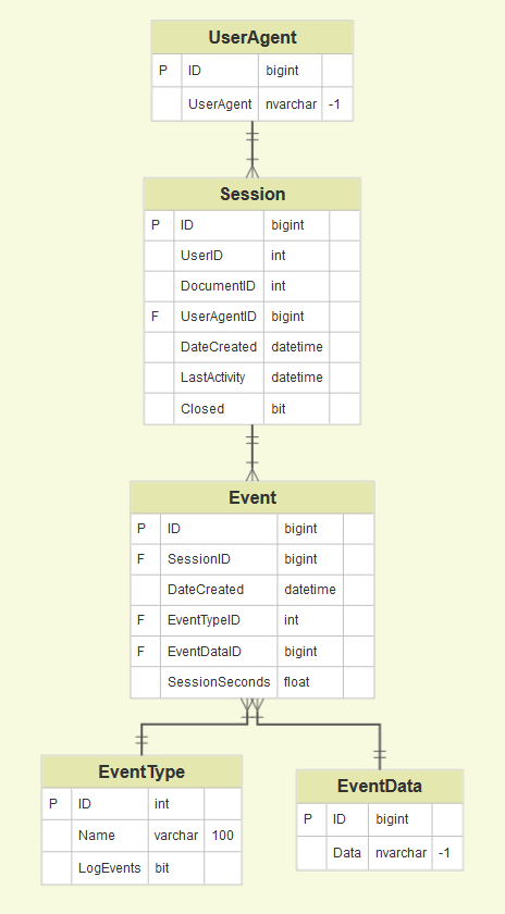
Here’s an example of a very basic database structure generated from data.
If you want to create a new plan, you can also edit the generated diagram and collaborate with your team on what changes to make.
ERD notations guide
An ER Diagram contains entities, attributes, and relationships. In this section, we will go through the ERD symbols in detail.
Entity
An ERD entity is a definable thing or concept within a system, such as a person/role (e.g. Student), object (e.g. Invoice), concept (e.g. Profile) or event (e.g. Transaction) (note: In ERD, the term «entity» is often used instead of «table», but they are the same). When determining entities, think of them as nouns. In ER models, an entity is shown as a rounded rectangle, with its name on top and its attributes listed in the body of the entity shape. The ERD example below shows an example of an ER entity.
Entity Attributes
Also known as a column, an attribute is a property or characteristic of the entity that holds it.
An attribute has a name that describes the property and a type that describes the kind of attribute it is, such as varchar for a string, and int for integer. When an ERD is drawn for physical database development, it is important to ensure the use of types that are supported by the target RDBMS.
The ER diagram example below shows an entity with some attributes in it.
Primary Key
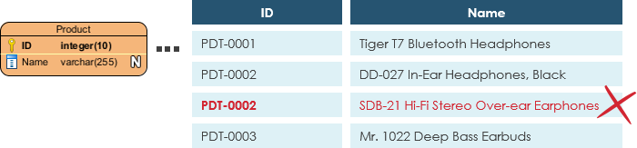
Also known as PK, a primary key is a special kind of entity attribute that uniquely defines a record in a database table. In other words, there must not be two (or more) records that share the same value for the primary key attribute. The ERD example below shows an entity ‘Product’ with a primary key attribute ‘ID’, and a preview of table records in the database. The third record is invalid because the value of ID ‘PDT-0002’ is already used by another record.
Foreign Key
Also known as FK, a foreign key is a reference to a primary key in a table. It is used to identify the relationships between entities. Note that foreign keys need not be unique. Multiple records can share the same values. The ER Diagram example below shows an entity with some columns, among which a foreign key is used in referencing another entity.

Relationship
A relationship between two entities signifies that the two entities are associated with each other somehow. For example, a student might enroll in a course. The entity Student is therefore related to Course, and a relationship is presented as a connector connecting between them.
Cardinality
Cardinality defines the possible number of occurrences in one entity which is associated with the number of occurrences in another. For example, ONE team has MANY players. When present in an ERD, the entity Team and Player are inter-connected with a one-to-many relationship.
In an ER diagram, cardinality is represented as a crow’s foot at the connector’s ends. The three common cardinal relationships are one-to-one, one-to-many, and many-to-many.
One-to-One cardinality example
A one-to-one relationship is mostly used to split an entity in two to provide information concisely and make it more understandable. The figure below shows an example of a one-to-one relationship.

One-to-Many cardinality example
A one-to-many relationship refers to the relationship between two entities X and Y in which an instance of X may be linked to many instances of Y, but an instance of Y is linked to only one instance of X. The figure below shows an example of a one-to-many relationship.

Many-to-Many cardinality example
A many-to-many relationship refers to the relationship between two entities X and Y in which X may be linked to many instances of Y and vice versa. The figure below shows an example of a many-to-many relationship. Note that a many-to-many relationship is split into a pair of one-to-many relationships in a physical ERD. You will know what a physical ERD is in the next section.

И снова про бизнес-процессы: живой опыт без теории
«Вы не любите кошек? Вы просто не умеете их готовить» (к/ф «Альф»)
Есть разные подходы к тому, как выделять и классифицировать бизнес-процессы, есть с десяток разных нотаций, в которых их можно описывать, есть целый ряд правил, по которым следует выявлять зоны неоптимальности и предлагать улучшения. По сути, мы с вами получаем в руки ящик с инструментами. А профессионализм аналитика заключается в выборе того, инструмента, который лучше всего подойдет для конкретной бизнес-задачи конкретного предприятия. В статье я хочу поделиться результатами осмысления собственных проектов и теми правилами, которые считаю важным и нужным учитывать при анализе и оптимизации бизнес-процессов.
Why use ER Diagrams?
Here, are prime reasons for using the ER Diagram
- Helps you to define terms related to entity relationship modeling
- Provide a preview of how all your tables should connect, what fields are going to be on each table
- Helps to describe entities, attributes, relationships
- ER diagrams are translatable into relational tables which allows you to build databases quickly
- ER diagrams can be used by database designers as a blueprint for implementing data in specific software applications
- The database designer gains a better understanding of the information to be contained in the database with the help of ERP diagram
- ERD Diagram allows you to communicate with the logical structure of the database to users
Weak Entities
A weak entity is a type of entity which doesn’t have its key attribute. It can be identified uniquely by considering the primary key of another entity. For that, weak entity sets need to have participation.
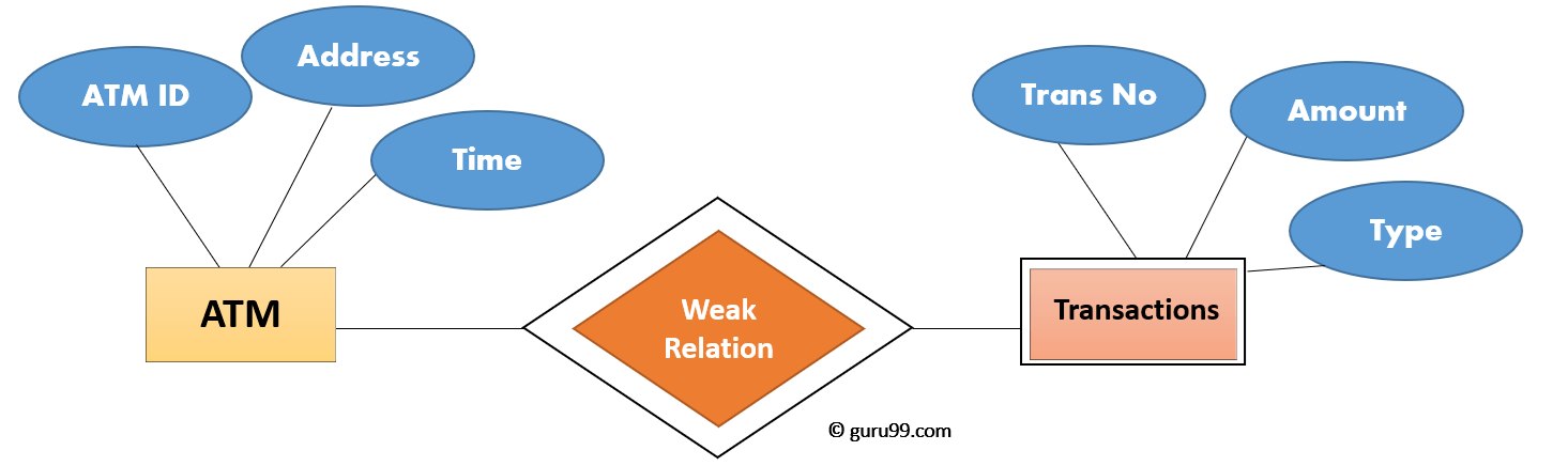
In above ER Diagram examples, «Trans No» is a discriminator within a group of transactions in an ATM.
Let’s learn more about a weak entity by comparing it with a Strong Entity
| Strong Entity Set | Weak Entity Set |
| Strong entity set always has a primary key. | It does not have enough attributes to build a primary key. |
| It is represented by a rectangle symbol. | It is represented by a double rectangle symbol. |
| It contains a Primary key represented by the underline symbol. | It contains a Partial Key which is represented by a dashed underline symbol. |
| The member of a strong entity set is called as dominant entity set. | The member of a weak entity set called as a subordinate entity set. |
| Primary Key is one of its attributes which helps to identify its member. | In a weak entity set, it is a combination of primary key and partial key of the strong entity set. |
| In the ER diagram the relationship between two strong entity set shown by using a diamond symbol. | The relationship between one strong and a weak entity set shown by using the double diamond symbol. |
| The connecting line of the strong entity set with the relationship is single. | The line connecting the weak entity set for identifying relationship is double. |
2 Построение концептуальной модели
Выше были отображены основные сущности, но не отображены роли пользователей, хотя их тоже должна хранить система. Они показаны ниже на ER-диаграмме в нотации Чена .

На диаграмме выделены роли кассира и менеджера, а также основные отношения между сущностями. На диаграмме нет роли администратора, но его роль заключается в:
- создании всех таблиц базы;
- добавлении залов и рядов в них;
- добавлении кассиров и менеджеров.
На диаграмме не отражена роль посетителя, так как:
- билет не содержит информации о том, кто его купил (посетитель может подарить билет другу);
- система вообще не хранит информацию о посетителях;
- покупку билета он осуществляет через общение с кассиром вне системы;
- никакие данные в базе посетитель самостоятельно изменить не может.
На диаграмме проставлены кратности связей, например, видно, что один менеджер может добавить много (N) прокатов. В этой базе не оказалось связей типа N:M, сложных или рекурсивных связей — такие связи являются препятствиями в проектировании и решаются изменением ее структуры.
Для формирования схемы данных необходимо сначала дополнить ER-диаграмму реквизитами сущностей (уточнить ее) — результат приведен на рисунке.

- система не должна позволять продавать несколько билетов на одно и то же место при одном показе фильма. Это значит, что вторичным ключем для Билета должен быть кортеж (id_screening, row, seat). Однако, тогда нет необходимости в id билета — на билеты не ссылается ни одна таблица, это поле может быть удалено. Изначально id был добавлен потому, что обычно на билетах в кинотеатрах печатается номер;
- билет хранит поле id_hall, это было сделано для того, чтобы посетитель кинотеатра мог найти свой кинозал. Однако, билет, выдаваемый пользователю — это не тоже самое, что информация о билетах, хранимая в базе данных. Билет базы данных хранит также поле id_screening, а Показ уже ссылается на id_hall. Таким образом, в базе нет смысла хранить id_hall в таблице билетов.
Исправленная ER-диаграмма приведена ниже:

Таблица менеджеров и кассиров не объединены в таблицу Users так как вопросы разграничения прав доступа в различных СУБД решаются по-разному. Так, в MS SQL пользователи добавляются с помощью специальных запросов типа:
при этом вообще нет необходимости хранить информацию об их логинах и паролях в таблицах. Однако, вопросы разграничения доступа решаются позже — на этапе физического проектирования.
Conceptual, Logical and Physical data models
An ER model is typically drawn at up to three levels of abstraction:
While all the three levels of an ER model contain entities with attributes and relationships, they differ in the purposes they are created for and the audiences they are meant to target.
A general understanding to the three data models is that business analyst uses a conceptual and logical model to model the business objects exist in the system, while database designer or database engineer elaborates the conceptual and logical ER model to produce the physical model that presents the physical database structure ready for database creation. The table below shows the difference between the three data models.
Conceptual model vs Logical model vs Data model:
| ERD features | Conceptual | Logical | Physical |
|---|---|---|---|
| Entity (Name) | Yes | Yes | Yes |
| Relationship | Yes | Yes | Yes |
| Columns | Yes | Yes | |
| Column’s Types | Optional | Yes | |
| Primary Key | Yes | ||
| Foreign Key | Yes |
Conceptual data model
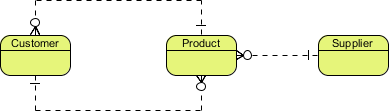
Conceptual ERD models the business objects that should exist in a system and the relationships between them. A conceptual model is developed to present an overall picture of the system by recognizing the business objects involved. It defines what entities exist, NOT which tables. For example, ‘many to many’ tables may exist in a logical or physical data model but they are just shown as a relationship with no cardinality under the conceptual data model.
Conceptual data model example

NOTE: Conceptual ERD supports the use of generalization in modeling the ‘a kind of’ relationship between two entities, for instance, Triangle, is a kind of Shape. The usage is like generalization in UML. Notice that only conceptual ERD supports generalization.
Logical data model
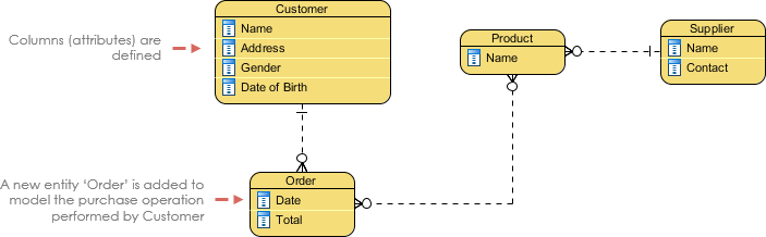
Logical ERD is a detailed version of a Conceptual ERD. A logical ER model is developed to enrich a conceptual model by defining explicitly the columns in each entity and introducing operational and transactional entities. Although a logical data model is still independent of the actual database system in which the database will be created, you can still take that into consideration if it affects the design.
Logical data model example
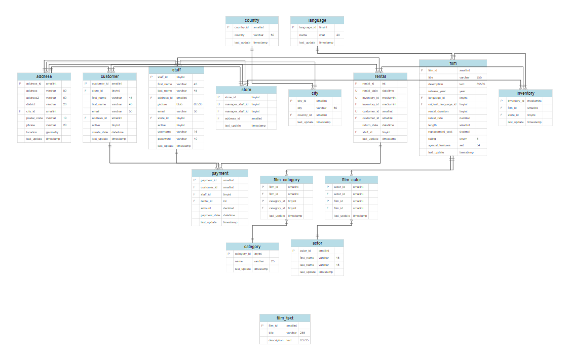
Physical data model
Physical ERD represents the actual design blueprint of a relational database. A physical data model elaborates on the logical data model by assigning each column with type, length, nullable, etc. Since a physical ERD represents how data should be structured and related in a specific DBMS it is important to consider the convention and restriction of the actual database system in which the database will be created. Make sure the column types are supported by the DBMS and reserved words are not used in naming entities and columns.
yEd Graph Editor

yEd Graph Editor is quite a popular software to create different types of diagrams, including computer network, flowchart, UML, BPMN, SBGN, etc. You can also use it to draw ER diagram.
To draw ER diagram in yEd Graph Editor:
The symbols used to create ER diagrams can be accessed from Palette window at right. You can add a simple entity, weak entity, entity with attributes, relationship between two entities, weak relationship, attributes, multivalued attributes, primary key attribute, derived attribute, and connectors, to create a desired entity relationship diagram. From the Properties tab at right, you can customize the text font, fill color, line color, label properties, etc. From the same tab, you can add a URL and description too.
Here are some other key features of this ER diagram maker:
- On the main interface, there are various compact windows named Overview (preview of ER diagram), Neighborhood (displays selected part), and Structure View (hierarchical structure of graph).
- From the Layout menu, you can choose the layout of ER diagram as Hierarchal, Organic, Orthogonal, Circular, Tree, Radial, Series Parallel, etc. The layout is customizable, e.g. for radial layout, you can customize minimal circle distance, minimal node distance, maximum child sector size, routing style, etc.
- The Tools menu provides various handy features including: Analyze Graph (to analyze graph structure in terms of node count, visual, topology, etc.), Centrality Measure (determining importance of a node in graph), Colorize Graph (to assign colors to nodes), Create Graph (create new graphs from the scratch like grid, tree, planar, and random), Geometric Transformation, etc. Also, from Grouping menu, you can create a group node.
- You can save the created ERD project as GraphML, YGF, GML, TGF, etc. projects. But, you can export ER diagram in a good range of formats, such as JPEG, BMP, HTML, PDF, PNG, SVG, EPS, etc.
yEd Graph Editor is one of the best er diagram software for Windows.
Что такое диаграмма EER?
Когда приложение стало сложным, традиционной ER-модели оказалось недостаточно для построения сложной диаграммы. Поэтому модель ER получила дальнейшее развитие. Это известно как расширенная диаграмма ER. К существующей модели ER на диаграмме Enhanced ER (EER) добавлены три концепции. Это обобщение, специализация и агрегирование. В общем, сущности более низкого уровня могут быть объединены для создания сущности более высокого уровня. Специализация противоположна обобщению. По специализации сущности высокого уровня можно разделить на сущности более низкого уровня. Агрегация — это процесс, когда отношение между двумя объектами рассматривается как единое целое.

Согласно приведенной выше ER-диаграмме сущности Student и Lecturer являются сущностями Person. При движении снизу вверх обобщает сущности Student и Lecturer в сущность Person. Это подход снизу вверх. При переходе сверху вниз сущность Person может быть дополнительно специализирована на Student и Lecturer. Это подход сверху вниз. Атрибуты «Имя» и «город» объекта «Лицо» принадлежат сущности «Студент», а также сущности «Лектор». Сущность Student имеет свой собственный атрибут student_id, а сущность Lecturer имеет свой lecturer_id.
Пример агрегации следующий.

Согласно приведенной выше диаграмме ER, отношения между экзаменационным центром и экзаменом вместе действуют как единое целое. Вся эта сущность находится во взаимосвязи с сущностью Студент. Когда студент посещает экзаменационный центр, он или она спросит как о центре, так и об экзамене. Следовательно, когда отношение между двумя объектами рассматривается как единое целое, это агрегирование.
Conceptual, Logical and Physical data models
An ER model is typically drawn at up to three levels of abstraction:
While all the three levels of an ER model contain entities with attributes and relationships, they differ in the purposes they are created for and the audiences they are meant to target.
A general understanding to the three data models is that business analyst uses a conceptual and logical model to model the business objects exist in the system, while database designer or database engineer elaborates the conceptual and logical ER model to produce the physical model that presents the physical database structure ready for database creation. The table below shows the difference between the three data models.
Conceptual model vs Logical model vs Data model:
| ERD features | Conceptual | Logical | Physical |
|---|---|---|---|
| Entity (Name) | Yes | Yes | Yes |
| Relationship | Yes | Yes | Yes |
| Columns | Yes | Yes | |
| Column’s Types | Optional | Yes | |
| Primary Key | Yes | ||
| Foreign Key | Yes |
Conceptual data model
Conceptual ERD models the business objects that should exist in a system and the relationships between them. A conceptual model is developed to present an overall picture of the system by recognizing the business objects involved. It defines what entities exist, NOT which tables. For example, ‘many to many’ tables may exist in a logical or physical data model but they are just shown as a relationship with no cardinality under the conceptual data model.
Conceptual data model example
NOTE: Conceptual ERD supports the use of generalization in modeling the ‘a kind of’ relationship between two entities, for instance, Triangle, is a kind of Shape. The usage is like generalization in UML. Notice that only conceptual ERD supports generalization.
Logical data model
Logical ERD is a detailed version of a Conceptual ERD. A logical ER model is developed to enrich a conceptual model by defining explicitly the columns in each entity and introducing operational and transactional entities. Although a logical data model is still independent of the actual database system in which the database will be created, you can still take that into consideration if it affects the design.
Logical data model example

Physical ERD represents the actual design blueprint of a relational database. A physical data model elaborates on the logical data model by assigning each column with type, length, nullable, etc. Since a physical ERD represents how data should be structured and related in a specific DBMS it is important to consider the convention and restriction of the actual database system in which the database will be created. Make sure the column types are supported by the DBMS and reserved words are not used in naming entities and columns.
What is ER Diagram?
ER Diagram stands for Entity Relationship Diagram, also known as ERD is a diagram that displays the relationship of entity sets stored in a database. In other words, ER diagrams help to explain the logical structure of databases. ER diagrams are created based on three basic concepts: entities, attributes and relationships.
ER Diagrams contain different symbols that use rectangles to represent entities, ovals to define attributes and diamond shapes to represent relationships.
At first look, an ER diagram looks very similar to the flowchart. However, ER Diagram includes many specialized symbols, and its meanings make this model unique. The purpose of ER Diagram is to represent the entity framework infrastructure.